
Table Of Content
- 1 Definition of Transformer
- 2 Working Principle of Transformer
- 3 Types of Transformer
In the realm of electricity, transformers play a pivotal role in ensuring the efficient transmission and distribution of power. They are essential for adapting voltage levels to suit different needs, whether for long-distance transmission or local consumption. Moreover, their versatility makes them a cornerstone of electrical systems. This ability reduces energy losses and ensures safe delivery, making transformers a cornerstone of electrical systems. Therefore, it is essential to learn about Transformer: Definition, Working Principle, Types, and Applications
Transformers not only make household appliances functional but also power large-scale industrial processes. Their role spans from enabling everyday conveniences to supporting critical infrastructure. With their simple yet powerful design, transformers stand as a testament to the ingenuity of electrical engineering and continue to shape how electricity powers the modern world. Below is a detailed discussion of Transformer: Definition, Working Principle, Types, and Applications
Definition of Transformer
A transformer is a static device that transfers electrical energy from one electrical circuit to another through a magnetic field without changing the frequency. It works on the principle of mutual induction, allowing electrical energy to transfer without any physical connection between the circuits.
In simple terms, a transformer changes (or “transforms”) the voltage level of electricity. This adjustment is necessary to optimize the power for various applications, from high-voltage transmission lines to the low-voltage electricity used in homes and industries. Transformer: Definition, Working Principle, Types, and Applications provide a deeper understanding of how these devices function, from their basic operation to the different types and their specific roles in electrical systems.
Working Principle of Transformer
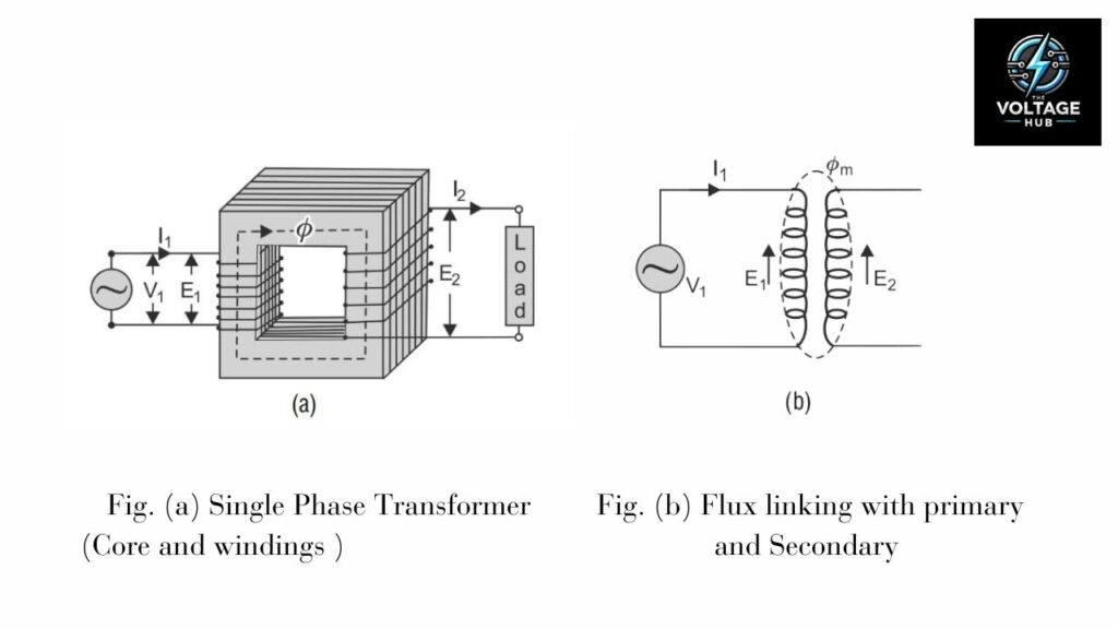
A transformer is a vital electrical device that operates on the principle of electromagnetic induction to transfer electrical energy between two or more circuits. It plays a crucial role in modern electrical systems by enabling the efficient transmission and distribution of power. The working principle of a transformer revolves around Faraday’s Law of Electromagnetic Induction and the phenomenon of mutual induction, where a changing magnetic flux induces an electromotive force (EMF) in a nearby coil.
The operation of a transformer begins with the application of an alternating current (AC) to its primary winding. This current flows in cycles, continuously varying in magnitude and direction. As the current passes through the primary winding, it generates a magnetic field around it. In contrast to a direct current (DC), which creates a steady magnetic field, an AC produces a time-varying magnetic field that oscillates in sync with the frequency of the current. This oscillating field is the cornerstone of transformer operation, as it leads to the generation of a time-varying magnetic flux.
The primary winding directs the magnetic flux through the transformer’s core. The core, typically made of high-permeability material such as laminated iron, provides a path for the flux and, as a result, enhances the magnetic coupling between the windings. The flux alternates in polarity and strength as the AC in the primary winding changes, creating a continuously changing magnetic field within the core. This flux not only links the primary winding but also extends to the secondary winding, ensuring that both windings share the same magnetic environment.
The changing magnetic flux in the core interacts with the secondary winding, inducing an electromotive force (EMF) in it. Faraday’s Law of Electromagnetic Induction governs this phenomenon. It states that the coil induces an EMF directly proportional to the rate of change of magnetic flux through the coil. Mathematically, Faraday’s Law expresses as:

Here, N represents the number of turns in the winding, and dΦ/dt is the rate of change of the magnetic flux. The negative sign indicates Lenz’s Law, which states that the induced EMF opposes the change in flux that causes it.
The voltage induced in the secondary winding depends on the number of turns in the winding relative to the primary winding. We express this relationship, known as the turns ratio, as:

In this equation, Vs and Vp are the voltages in the secondary and primary windings, respectively, whereas Ns and Np represent the number of turns in each winding. If the secondary winding has more turns than the primary winding (Ns >Np), the transformer increases the voltage, and we refer to it as a step-up transformer. Conversely, if the secondary winding has fewer turns (Ns<Np), it becomes a step-down transformer.
While the transformer can transform the voltage, it conserves power between the primary and secondary windings, except for minor losses. This principle, based on the conservation of energy, we express as:

Here, Pp and Ps are the power in the primary and secondary windings, and Ip and Is are the respective currents. This means that any increase in voltage on the secondary side results in a proportional decrease in current, and vice versa. For instance, in a step-up transformer, while the voltage increases, the current decreases, ensuring that the power remains constant.
The efficiency of a transformer largely depends on its ability to minimize losses. Ideal transformers assume no losses, but real-world applications dissipate some energy as heat due to core losses (caused by hysteresis and eddy currents in the core material) and copper losses (due to the resistance of the windings). However, advanced design techniques, such as using laminated cores and high-quality winding materials, help reduce these losses, achieving efficiencies exceeding 95% in most modern transformers.
The entire operation of a transformer relies on mutual induction, a phenomenon where a change in current in one coil induces a voltage in a nearby coil. The shared magnetic flux makes this mutual interaction possible, linking the primary and secondary windings efficiently. The quality of this linkage, influenced by the design of the core and the arrangement of the windings, determines the efficiency of the energy transfer.
Types of Transformer
Transformers are classified into various types based on their design, construction, and applications. Each type serves a specific purpose in the electrical system, from voltage regulation to energy distribution. Transformer: Definition, Working Principle, Types, and Applications are key to understanding their role in modern electrical systems. By using electromagnetic induction to transfer energy efficiently, transformers adapt voltage levels for diverse requirements. Below is a detailed discussion of the different types of transformers, highlighting their unique features and applications in ensuring the seamless operation of power systems.
1. Based on Voltage Levels
We categorize transformers primarily by their function in stepping up or stepping down voltage levels.
a. Step-Up Transformer
A step-up transformer increases the voltage from the primary to the secondary winding. It has more turns in the secondary winding than in the primary winding, thereby allowing it to raise the voltage for efficient long-distance power transmission. Power plants commonly use step-up transformers to step up the generated voltage for transmission over high-voltage lines.
b. Step-Down Transformer
A step-down transformer reduces the voltage from the primary to the secondary winding. It has fewer turns in the secondary winding than in the primary, which means it lowers the voltage.. Distribution networks widely use step-down transformers to lower the voltage to safe levels for residential and commercial use.
2. Based on Core Design
Additionally, transformers can also be classified by their core structure.
a. Core-Type Transformer
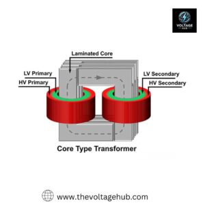
In core-type transformers, we place the windings around the two limbs of the core. The core reduces eddy current losses by using laminated steel. We typically use these transformers in high-voltage applications, such as power transmission systems, where efficiency is critical.
b. Shell-Type Transformer
In shell-type transformers, the core encloses the windings on both sides. This design provides better mechanical strength and magnetic shielding, making them suitable for low-voltage and high-current applications like electrical furnaces.
c. Berry-Type Transformer
Berry-type transformers have a circular core with windings distributed symmetrically. We use these less common transformers in specific industrial applications requiring compact designs.
3. Based on the Number of Phases
We categorize transformers by the number of phases they handle.
a. Single-Phase Transformer
Systems operating on a single-phase power supply use single-phase transformers. We commonly find these in residential applications, where power requirements are relatively low.
b. Three-Phase Transformer
Three-phase transformers are designed to handle three-phase power, which is the standard for industrial and commercial systems. They can be constructed as a single three-phase unit or as a bank of three single-phase transformers. They are widely used in power generation, transmission, and distribution systems.
4. Based on Winding Arrangement
Furthermore, the configuration of the windings also determines the type of transformer.
a. Two-Winding Transformer
This type has two separate windings, a primary and a secondary, with no electrical connection between them. Energy transfer occurs through magnetic flux in the core. These are used for general voltage transformation.
b. Auto-Transformer
An auto-transformer has a single winding that serves both as the primary and secondary winding. Part of the winding is common to both. Auto-transformers are more efficient and compact yet lack electrical isolation, making them suitable for voltage regulation applications.
5. Based on Cooling Methods
Cooling is critical for maintaining the performance and longevity of transformers. They are classified by their cooling techniques.
a. Air-Cooled Transformer
Air-cooled or dry-type transformers rely on natural or forced air circulation to cool the windings. They are typically used in indoor applications, such as office buildings and shopping centers, because oil-based transformers might pose a fire risk.
b. Oil-Cooled Transformer
Oil-cooled transformers use mineral oil or synthetic fluids to dissipate heat. The oil circulates naturally or pumps force it, carrying heat away from the windings to external radiators or fans. We widely use these transformers in outdoor power distribution systems.
c. Water-Cooled Transformer
Water-cooled transformers use water as the cooling medium, often in conjunction with oil. These are typically used in large industrial applications, such as power plants, where efficient cooling is essential.
6. Based on Special Features
Certain transformers are designed with unique features for specific requirements.
a. Phase-Shifting Transformer
These are used to control the phase angle between input and output voltages, helping manage power flow in transmission lines.
b. Rectifier Transformer
These are used in conjunction with rectifiers to convert AC to DC for applications like electroplating and traction systems.
c. HVDC Converter Transformer
High-Voltage Direct Current (HVDC) transformers are used in HVDC transmission systems to facilitate the conversion of AC to DC and vice versa.
d. Earthing Transformer
Earthing transformers provide a neutral point for grounding systems in three-phase systems. They are commonly used in substations.
7. Based on Applications
Transformers are also classified based on their specific uses.
a. Power Transformer
We use power transformers in transmission networks to step up or step down voltage levels at high power. They are designed for high efficiency and operate continuously at near-full load. Examples include transformers in power generation stations and substations.
b. Distribution Transformer
Distribution transformers step down the voltage to levels suitable for residential, commercial, or industrial use. They are designed for lower efficiency since they operate at partial loads most of the time.
c. Instrument Transformer
Instrument transformers are used to measure voltage, current, or power in electrical systems. These include:
Current Transformer (CT): Steps down high currents to safe levels for measurement and protection systems.
Potential Transformer (PT): Steps down high voltages for use in measuring instruments.
d. Isolation Transformer
Isolation transformers provide electrical isolation between the primary and secondary windings without stepping up or down the voltage. They are used for safety purposes and to eliminate ground loops in sensitive equipment.
e. Furnace Transformer
Furnace transformers are specialized for supplying power to electric furnaces, where high current and low voltage are required.
f. Welding Transformer
Welding transformers step down voltage and provide high current suitable for welding applications. They are designed for intermittent operation and robust performance.
Applications of Transformers
Transformers find applications across a vast spectrum of industries and systems:
1. Power Generation and Transmission
- Transformers are used in power plants to step up voltage for transmission.
- Substations use step-down transformers to distribute electricity locally.
2. Industrial Applications
- Heavy machinery requires specific voltage levels, which transformers provide efficiently.
3. Commercial and Residential Use
- Small transformers in appliances like chargers and televisions adapt the mains supply to the required voltage.
4. Renewable Energy Systems
- Transformers enable the integration of solar, wind, and hydroelectric power into the grid.
5. Electronics
- Transformers in electronic devices ensure the correct operating voltage for circuits.
Conclusion
Transformers are the backbone of electrical systems, enabling the safe, efficient, and reliable distribution of power. From powering homes and industries to integrating renewable energy sources, their role is indispensable in modern society. By understanding Transformer: Definition, Working Principle, Types, and Applications , we appreciate the unseen work behind the electrical conveniences we often take for granted.
Whether stepping up voltage for transmission or stepping it down for consumption, transformers play a crucial role in efficiently transferring electrical energy within the power infrastructure. Transformer: Definition, Working Principle, Types, and Applications are essential to understanding their significance in modern electrical systems.
FAQs
[sc_fs_multi_faq headline-0=”p” question-0=”1. What is a transformer and why is it important?” answer-0=”A transformer is an electrical device that transfers energy between circuits by electromagnetic induction. It is essential for adapting voltage levels to efficiently transmit and distribute electricity.” image-0=”” headline-1=”p” question-1=”2. How does a transformer work?” answer-1=”A transformer works on the principle of electromagnetic induction, where a changing magnetic field in the primary coil induces a voltage in the secondary coil, enabling energy transfer. ” image-1=”” headline-2=”p” question-2=”3. What are the main types of transformers?” answer-2=”Common types include step-up transformers, step-down transformers, isolation transformers, autotransformers, and instrument transformers, each serving unique purposes in electrical systems.” image-2=”” headline-3=”p” question-3=”4. Where are transformers used?” answer-3=”Transformers are used in power generation, transmission, and distribution systems, as well as in industrial processes, home appliances, and electronic devices.” image-3=”” headline-4=”p” question-4=”5. What is the difference between a step-up and a step-down transformer?” answer-4=”A step-up transformer increases voltage for long-distance transmission, while a step-down transformer reduces voltage for safe use in homes and industries.” image-4=”” count=”5″ html=”true” css_class=””]
